With the arrival of Winter, it’s been getting cold again. My apartment has this very specific problem that the kitchen is not covered by central heating, so it becomes a very unpleasant place to be during the cold season. Last year, I finally got around to doing something about this, and I splurged on an infrared heating panel, made by a certain Hungarian company whose name rhymes with “hydrofoil”. In general, I was quite impressed with how much of a difference could such a small 350W unit make, even though I was a little unhappy about its Internet-connected thermostat. The device itself is unfortunately a little bulky, though it helps that it’s masquerading as a picture that you can just hang on a wall. Plus, when the heating season is over, you can just put it away.

So, this year, when I was taking the heater out of storage, I accidentally dropped it on the floor, and after that it wouldn’t turn on again. Clumsiness is not covered by warranty, so that’s a loss, right? Nope! I actually managed to fix the unit myself, and I also replaced the thermostat with a much better one while I was at it! This is an account of how it went.
Disclaimers
THIS ARTICLE IS PROVIDED “AS-IS” AND IS MEANT FOR EDUCATIONAL PURPOSES ONLY. IT IS AN ACCOUNT OF EVENTS AND NOT A GUIDE TO BE FOLLOWED. THE AUTHOR OF THIS ARTICLE DOES NOT TAKE RESPONSIBILITY FOR ANY DAMAGE CAUSED BY ATTEMPTS TO REPLICATE THE EVENTS DESCRIBED IN IT.
HANDLING HIGH VOLTAGE WITHOUT SPECIAL TRAINING CAN CAUSE DEATH OR SERIOUS INJURY. DO NOT OPEN THE CASE OF A HIGH-VOLTAGE DEVICE IF YOU DO NOT HAVE SPECIAL TRAINING.
OPENING THE CASE OF ANY ELECTRONIC DEVICE WILL VOID ITS WARRANTY.
Assessing the damage
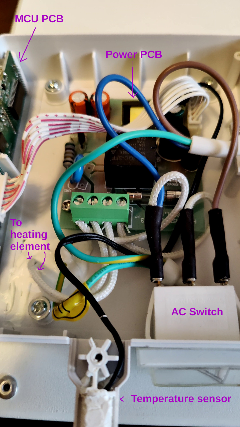
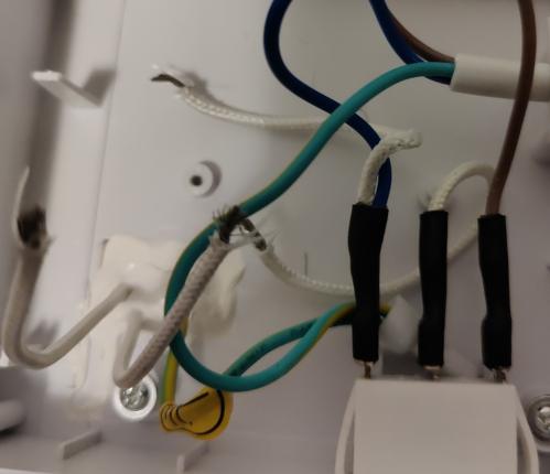
Opening the case reveals two printed circuit boards, a temperature sensor, and a power switch. Additionally, there are two thick wires that disappear into a glue-covered hole leading into the depth of the device. This must be the heating element connection. We’ll be observing both circuit boards in detail after removing them from the casing. But first…
Does the heating work?
If the heating element doesn’t work anymore, then the entire project is pointless, so that’s the first thing to check. I removed both PCBs, and then spent a little time studying them to verify my assumption: that unaltered mains voltage was meant to be applied to the heater. It was. I therefore temporarily connected both mains wires to the heater wires, held my breath, and then flipped the power switch. After a couple seconds, the surface of the device started getting warm, proving that the heating element had indeed survived the crash. Success!
Power PCB
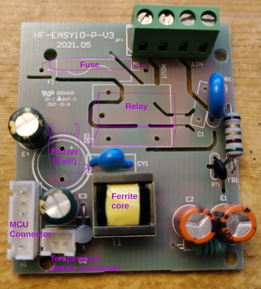
Most of the surface area of the large square board is dedicated to a power supply unit. It also contains a relay for toggling the heating element electronically, and a small buzzer, which acts as a source of annoying beeps. There is also a rainbow cable connection to the other PCB, and another two-wire connection to the temperature sensor.
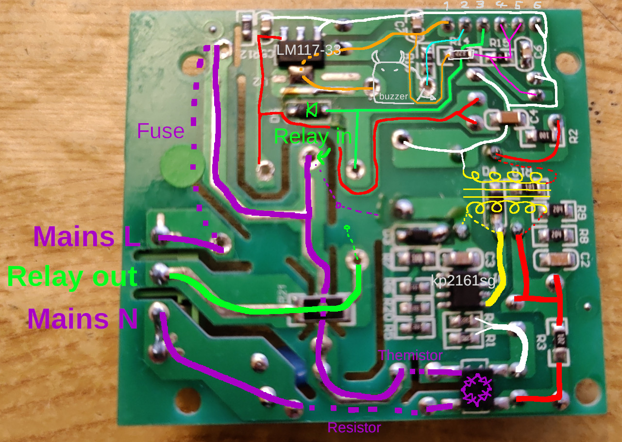
The underside is a bit busy, so let’s take it section by section:
Mains voltage section
We’ll start with the high voltage input in the lower-left, where you can see the purple “Mains” labels. One phase, marked “L” goes through a fuse (dashed line) and then branches off to become an input for the relay, and, through a thermistor, to a rectifier bridge in the bottom right. The other phase, marked “N”, goes to the other bridge input, passing through a resistor on the way.
When the relay coil is energized, the purple input path is connected to the thick bright green output path. When the board inside the device, this bright green path is then connected to the heating element. This is how we know that the heater is operating at mains voltage.
Switching power supply section
The bottom-right quarter of the board holds a switching power supply unit, which converts the rectified mains voltage (thick lines) to a smaller voltage (thin lines). I think this smaller voltage should be at around 5V level, as that is what the relay wants on its coils. The reason for my uncertainty will become apparent shortly.
Starting with the purple rectifier in the bottom right, on its right side are two DC current outputs, which go to the switching circuit, which consists of a chopper MOSFET, labelled KP2161SD, and a small transformer coil, labelled EPC13. The MOSFET “chops” the input voltage into a great number of tiny pulses, which allows the transformer to scale this signal down to a much smaller voltage. On the other side of transformer coils, only a simple capacitor is needed to convert this chopped signal back into a steady level DC that electronic components can use as power supply.
How does a switching power supply work
The main idea behind a switching power supply is the observation that the lower the frequency of the signal that needs to be converted, the heavier and bulkier transformer coils have to be. Since the mains power signal is only at 50Hz (60Hz in some countries), then a really big and heavy transformer is needed to convert it to a smaller voltage. This is why the traditional transformer-based power supplies for old laptops and phones were so big and heavy! The switching power supply works around this problem by chopping the signal into very high frequency pulses, which then require a much smaller transformer for the voltage conversion.
The low voltage section
The upper-right part of the board contains the two connectors, one to the other PCB (I labelled its terminals from 1 through 6), and another for the temperature sensor. In the top-center there is also an LM117-33, a very common voltage converter that creates the 3.3V power for the MCU board (orange line).
If you follow the thin red line from its source at the transformer, you will notice that it goes to the relay coil, and also to the input of the LM117-33. The corresponding white line serves as a ground reference for this converter, and also for many other parts of the circuit. The thin green line goes straight from the other PCB connector to the other side of the relay coil, and is most likely used for toggling the relay. There is also a diode to protect this 3.3V line from the higher voltage of the red line. When this line is pulled high (to 3.3V), then there is only 1.7V on the relay coil, which is not enough to close the switch. When the line is pulled low, then there is a full 5V across the coils, and the switch can close. The cyan line goes straight from the connector to the buzzer, and is certainly used to make infernal noises. Last but not least, there is a magenta line going from connector terminals #4 and #5, to the temperature sensor, and with a weak 22kΩ pull-up to the 3.3V line. This line is definitely used for getting the temperature, and the sensor itself is probably an analog resistive one.
The terminals of the connector that goes to the other PCB are described as follows:
- 3.3V power line for the other board,
- a control line for the infernal buzzer,
- relay control line (active low),
- a signal line for the temperature sensor,
- connected to #4,
- Ground power line.
MCU PCB
We will not be diving too deep into this board, as that’s not where the fault was, but I think it’s still pretty interesting.

The top side doesn’t that have much going on. We can see the LCD screen on the left, and some capacitive touch controls in the middle. A part of the WIFI+Bluetooth module is visible through a cut-out on the right, most likely its 2.4GHz antenna.
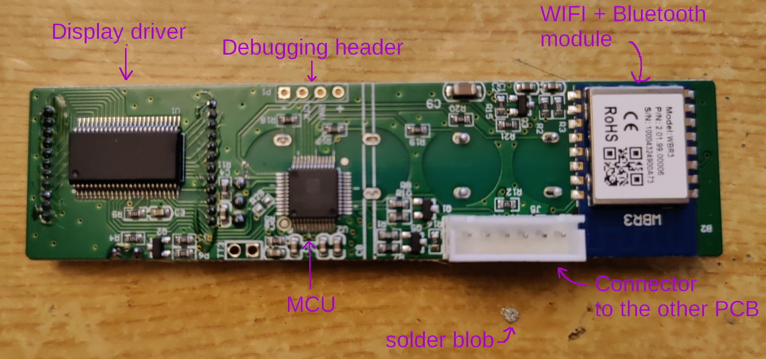
The bottom part features a big, unlabelled integrated circuit on the left. The number of lines coming from it to the LCD display leaves no doubt that this is a display driver. In the middle we have the logical brain of the device, a chip labeled “ME32F030C8T6”. It’s most likely an STM32F030xC, a 32-bit Cortex-M0-based ARM microcontroller. Above the MCU we can see a debugging header that is connected to the MCU’s serial wire debug port (SW-DP). It can apparently be used for programming the device, as well as troubleshooting its operation. On the right side of the board we have a connector that leads to the Power PCB, as well as the WIFI+Bluetooth module labeled WBR3.
Discovering the fault
Let’s take another look at the Power PCB:

I started my fault-searching procedure by measuring the voltage in several parts of the circuit. I started with the high-voltage lines, which indeed read as 230V AC. Past the rectifier bridge, the voltage became 320V DC, as expected. I didn’t have any tools to measure the performance of the chopper MOSFET, so I left it alone. Instead, I measured the voltage at the low-voltage side of the transformer, and it was 1.6V. Far cry from the expected 5V. This can mean that either the power supply itself is broken, or one of the 5V devices is drawing more current than the power supply can deliver, basically causing a brown-out. To eliminate the latter scenario, we have to take a look at two suspects: the LM117-33, and the relay.
I removed the relay from the board and tested again. The voltage level did not change, so the relay was not at fault. I then used hot air to remove the LM117-33, but it did not help either. Therefore, the fault must be either in the transformer core, or the chopper MOSFET. I would point out the transformer as the likely culprit, as coils made of thin wire tend to be susceptible to impact damage.
Unfortunately, this specific core is very hard to get where I live (in retail quantities), so it may not be possible to replace it. At this point, the project of repairing the device turned into a project of replacing its electronics. I will write more about it in part 2.

