
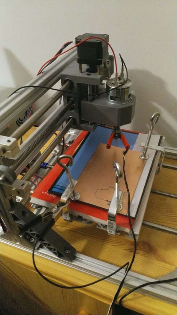
“Woodpecker” is a controller circuit board for some small and cheap CNC milling machines that one can order from China. These machines can be used, among others, for making DIY printed circuit boards.
“…but then I noticed a stack of smoke coming up from behind the screen. I stood up and looked at the mill. The probe cable was melting before my eyes. I rushed screaming to the power switch…”
While playing around with mine, I managed to damage it by accidentally applying high voltage to the “probe” terminal of the module. This caused the module’s microcontroller chip, an ATmega 328P to malfunction, and no longer respond to GRBL commands, effectively turning the machine into quite an expensive paperweight. Thankfully, I was able to replace the broken chip, and even program the replacement with a more recent version of GRBL firmware.
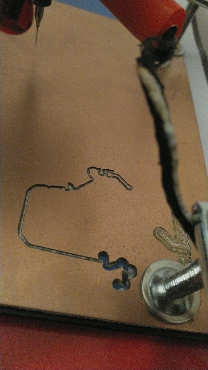
The trouble started when I first attempted to use a probe to generate a height-map of a copper laminate board. When making circuit boards, we want the mill to remove the ultra-thin layer of copper in certain places, while leaving intact as much of the underlying laminate as possible. Moreover, the board is never laid exactly level on the machine’s working area because of clamps holding it down. The difference in height sometimes can’t be seen with naked eye, but is guaranteed to be much larger than the thickness of the layer of copper that we want to remove.
The height-map approach solves this problem by having the machine take very exact height measurements at multiple points across the board. During a single measurement, the machine’s head is descending very slowly until it touches the board. Then the software saves the exact height at which contact took place, and then the machine makes another such measurement in another place.
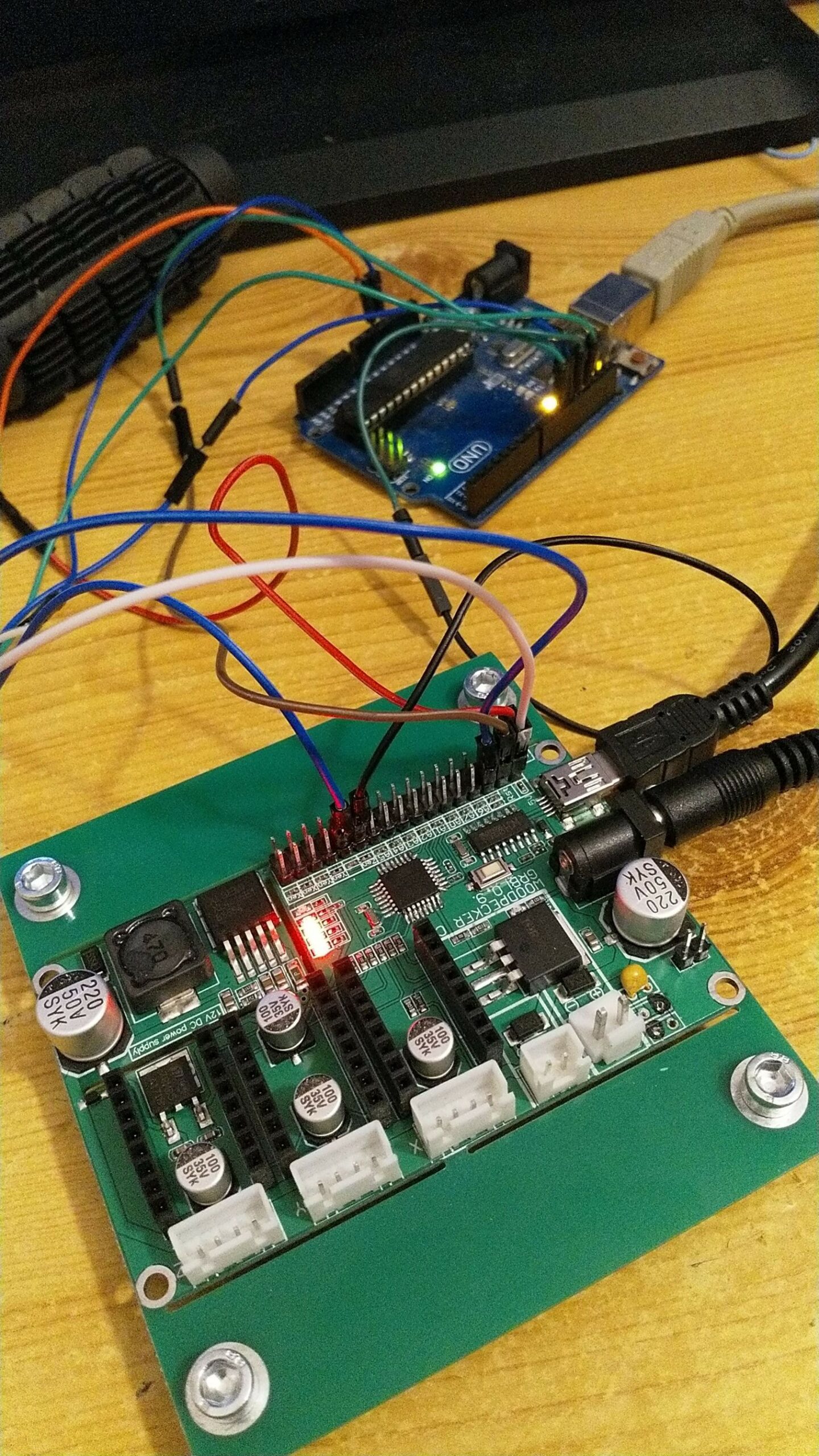
How does the machine tell that its tool is touching the board? The most common way is to attach electrodes to the tool and to the board itself. If the tool is touching the board, an electrical connection is made between the electrodes. This can be used to tell the machine that it’s reached the board. The woodpecker control module supports probing in a very simple way: one electrode is attached to the ground terminal, and the other one to the A5 pin on the module.
There’s a terrible catch however, and if unlike me you take the time to actually read the instructions, you’ll notice they want you to disconnect the spindle motor before attaching the probe electrodes. Why? Well, the spindle motor is connected in such a way that the positive terminal of its power line is connected to the motor’s casing. This means that the motor, its shaft, and the tool itself (!) has a potential difference of some +12V with respect to the module’s ground.
Now, what happens if you attach the probe in such conditions? The first thing that I noticed was that the spindle motor started spinning as soon as the alligator clip touched the tool. Thinking it was some software problem, I walked over to the computer intending to stop the spindle. I thought it was odd that bCNC claimed that the spindle was stationary, but then I noticed a stack of smoke coming up from behind the screen. I stood up and looked at the mill. The probe cable was melting before my eyes. I rushed screaming to the power switch. After ventilating the room, I ended up with melted isolation on the probe wires, and a non-responding control module.
What happened electrically was that the high voltage from the tool found its way to the ground through the alligator clip and the cable leading to the A5 pin on the control module, and finally through the microcontoller. The flow of current caused the motor to spin, even though it was not commanded to. Poor ATmega was not designed to have such high currents passing through it, so it must’ve broken down almost instantly. The current was also too high for the probe cable, which ran so hot the isolation was melting.
Lesson learned: Always check the voltage before making an arbitrary connection in a circuit you don’t know very well.
The good news was that the stepper motors, the spindle, and other parts of the control module appeared to be undamaged. So, I thought, perhaps the module could be saved by just replacing the ATmega? I’d have to program it though, but the Woodpecker is running GRBL, which is free software, and I found a discussion on the Internet (a gold mine of information, BTW) where people reported they were able to flash a more recent version of GRBL to the very same Woodpecker variant that I broke, so the plan didn’t seem impossible.
Since I didn’t have a spare ATmega on hand, I tried playing around with the broken chip first. I discovered that it was running very hot as a soon as power was switched on, suggesting a short-circuit. I guessed it was the pin that was connected to the probe when the accident happened, but I was too lazy to verify it with a meter. I extracted the ATmega from the module with the help of some hot air, and then managed to bend the offending pin slightly. Then I connected the power while pressing the chip to its footprint on the module. It became hot in an instant, so I decided to give up and wait for a replacement microcontroller.
When the replacement ATmega arrived, I promptly soldered it to the board, first with hot air and then touching every pin with soldering iron. I connected my Arduino Uno to act as a programmer, with connections just as shown in the blog post. I loaded the Adafruit In-system programming sketch, and tried to connect to the Atmega with avrdude. Unfortunately, avrdude could not read the device signature correctly: it was reading different gibberish for each attempt. I checked the connections with the meter and found a 100Ω resistor between the MISO pin and the connector. I wondered if it was messing up the timing.
I reloaded the Adafruit sketch with “slow mode” switched on and my suspicion proved to be correct – this time avrdude was able to read the device signature and even the fuse bits correctly. Unfortunately, the sketch did not support programming the flash memory with this speed, so I had to find something else. A brief search on GitHub turned up DEPlayground fork of ArduinoISP, which supports variable programming speed. Even its default setting was enough for the ATmega to catch up, and I was able to flash GRBL version 1.1 (an improvement over the board’s default v. 0.9) successfully. Now, what about the fuse bits?
Someone in the gold mine thread managed to read the fuses from an undamaged board, and the value was zero for both high and low fuses. This seems highly improbable, as such configuration would disable in-system programming, and also the reset pin. The presence of a reset button on the Woodpecker board strongly suggest a non-zero value for the high fuse at least. Perhaps some lock bit was making it impossible to read the fuses? I tried flashing various fuse bit combinations with various clock settings, but ATmega was showing no signs of life.
In desperation, I flashed the Arduino bootloader to the ATmega, followed by a sketch that would constantly output noise on the serial port, with various baud rates. None of it had any effect and the serial monitor remained stubbornly silent. In the end, I flashed the following values: 0xE2 for the L-fuse, and 0xDA for the H-fuse. This configuration used the microcontroller’s internal RC oscillator as the clock source, so it should “just work”. Then I flashed the GRBL again, disconnected the programmer and went to sleep.
The following day, when I got around to messing with the Woodpecker board again, I started with simply opening the serial port. Lo and behold, I was greeted with GRBL prompt! Perhaps severing all connections to the programmer board did the trick, I thought that just disconnecting the “slave reset” signal would’ve been enough.
Anyway, I reconnected the stepper motors and the spindle (gulp!), and ran some basic tests with bCNC. Everything turned out to be working fine, except for the x-axis motor – it was making noise, but not actually moving in either direction. Suspecting a cold solder, I’ve decided to reflow the ATmega. I applied generous amount of solder paste, and then proceeded to re-solder every single pin on the microcontroller with fresh tin. I made several short-circuits, and even partially melted the x-axis driver socket in the process. Oops. After fixing collecting the solder blobs and making sure the socket was still conductive, I reconnected the motors once again. This time everything was working correctly. What remained was the GRBL settings.
Someone posted the defaults for CNC1610, my model exactly, in the gold mine thread. I took the opportunity to modify them a bit: my machine is still new and not oiled very well, so the motors tend to skip during acceleration and deceleration. The problem was fixed by applying more conservative top speed and acceleration limits.
So, in the end I was able to not only recover my Woodpecker module, but also improve it with a more recent version of GRBL as well. In the process I learned a lot about using an Arduino for programming another board. I also managed to get the probe working, and I won’t be forgetting to disconnect the spindle before attaching the probe any time soon!
Resources
- [INFO] The gold mine thread
- [INFO] Connecting Arduino to Woodpecker CNC
- [LISTING] My GRBL settings
- [LISTING] DEPlayground’s Arduino in-system programming sketch
- [TOOL] Atmel AVR fuse calculator
- [DOCS] ATmega 328P datasheet
- [DOCS] Arduino Uno pinout
- [INFO] Upgrade your CNC
- [INFO] AVR Programming with Arduino
- [INFO] About Arduino ISP and bootloaders